

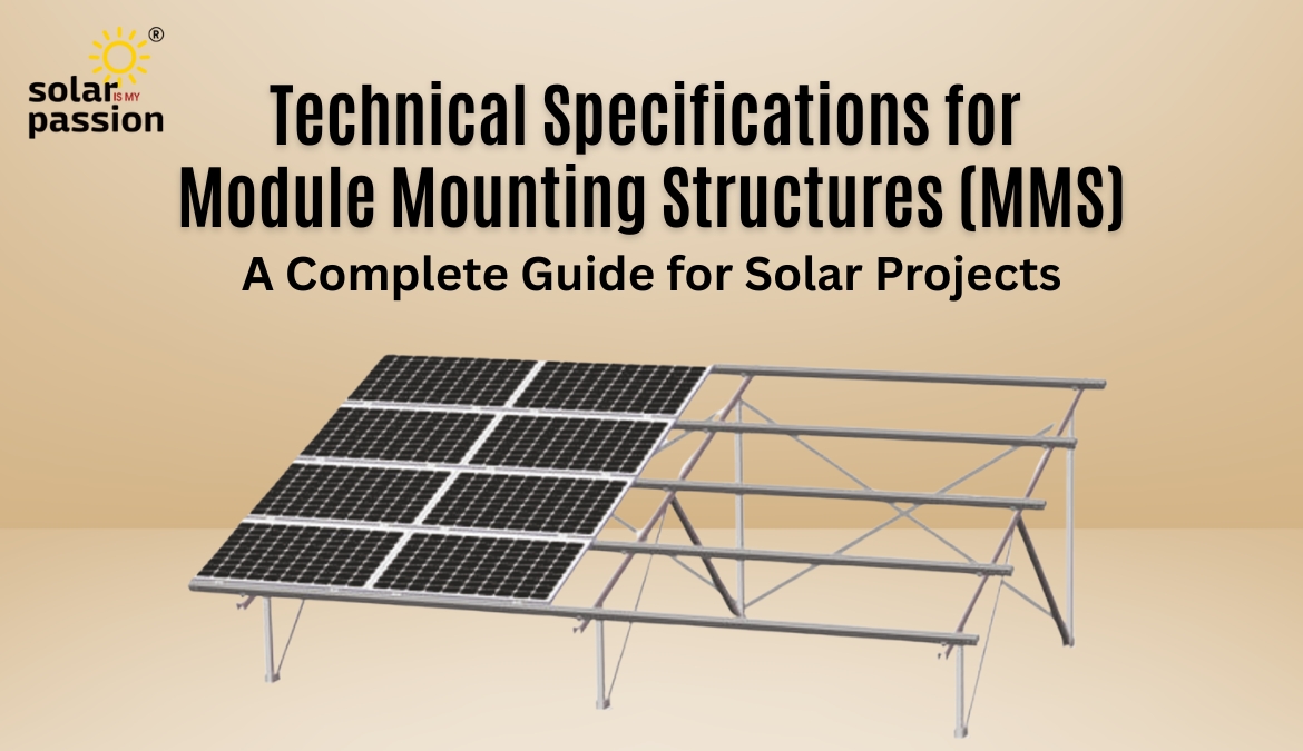
When we talk about solar power plants, most people focus on panels, inverters, and wiring. But there’s one part of the system that often gets overlooked — the Module Mounting Structure (MMS).
The MMS is not just a frame holding solar panels. It’s the backbone of the plant, ensuring that panels stay secure, angled correctly for maximum sunlight, and able to withstand decades of environmental stress — from scorching sun to heavy winds.
This guide dives deep into the scope, materials, design standards, structure types, and quality checks required for MMS, based on industry best practices and Indian Standards (IS).
1. Scope of Work
The scope for MMS covers everything from supply and fabrication to installation, erection, and acceptance testing. This includes:
- Complete structure along with all accessories, fasteners, and spare parts.
- Compliance with structural safety codes and performance requirements.
- Material choice between Hot Dip Galvanized Iron (GI), Aluminium, or Hot Dip Galvanized Mild Steel (MS).
For raised structures, Mild Steel (MS) is preferred because of its strength and cost-effectiveness.
2. Material Specifications
Steel MMS
- Steel must meet IS 2062:2011 requirements.
- Galvanization should comply with IS 4759, ensuring a protective zinc coating to prevent corrosion.
Aluminium MMS
- Aluminium alloy should be AA6063 T6 grade.
- For long life, aluminium should be coated or anodized to prevent oxidation and surface corrosion.
Fasteners & Clamps
- Bolts, nuts, and washers: Stainless Steel SS 304 or hot-dip galvanized for corrosion resistance.
- Panel mounting clamps: Made from aluminium, designed to hold panels under high wind loads and extreme weather.
Key Rule: All structural materials must be electrolytically compatible with module frames and fasteners to avoid galvanic corrosion.
3. Design & Performance Requirements
A good MMS design isn’t just about strength — it’s about performance, safety, and ease of maintenance.
- Angle of inclination: Optimized for the site’s latitude to ensure maximum sunlight throughout the year.
- Shadow-free generation: Structures must be arranged to avoid shading during generation hours.
- Wind speed resistance: Designed for the wind zone of the site with a minimum safety factor of 1.5.
- Ease of maintenance: Must allow easy cleaning, repair, and replacement of any panel without dismantling the array.
- Space optimization: Occupy minimum ground/roof space without compromising performance.
4. Types of Rooftop MMS Structures
4.1 Ballast Type (Non-Penetrating)
- No roof penetration — avoids leakage issues.
- Minimum clearance from roof: 70–150 mm for ventilation and easy cleaning.
- Weighted with M25 grade reinforced concrete blocks.
4.2 Tin Shed Mounting
- Design follows the existing slope of the tin shed.
- Two tilt options:
- Parallel to slope (best if slope faces true south).
- Adjusted tilt to match optimal solar angle.
- Clearance from shed: Minimum 100 mm at the lowest point.
- Base fixed on purlins with proper riveting.
- Minimum 2 mm thickness for all members.
4.3 RCC Elevated Structures
These are classified based on ground clearance height:
| Type | Height | Base Plate Thickness | Column & Member Specs | Notes |
|---|---|---|---|---|
| A | 300–1000 mm | 5 mm | Lip: 2 mm (70×40), C-Channel: 3 mm | Single portrait: min 500 mm clearance |
| B | 1000–2000 mm | 6 mm | Lip: 2 mm (80×50), C-Channel: 3 mm | Heavy-duty bolts required |
| C | 2000–3000 mm | 8 mm | Hollow section: 2.6 mm (50×50) | Bracing min 3 mm thickness |
| D – Super Elevated | >3000 mm | 10 mm base | Hollow section: 2.9 mm (60×60) | Extra sag bars if span > 3 m |
Key Design Points:
- All connections must be bolted (not welded on-site) for precision and maintenance ease.
- Minimum bolt sizes: 12 mm for leg-to-rafter, 10 mm for rafter-to-purlin.
- Fasteners: SS-304 for module mounting, others SS-304 or HDG Grade 8.8.
- Additional sag bars required if purlin span exceeds 3 meters.
5. Foundation Requirements
The foundation must match roof conditions and client preferences:
- Penetrating:
- Anchor bolts: 12 mm diameter, 100 mm length.
- RCC block: 400x400x300 mm, M20 grade.
- Non-Penetrating:
- J-bolts with Neto bond adhesive to secure foundation blocks without drilling.
6. Quality Standards & Testing
Every MMS must meet Indian Standards (IS) for material quality and fabrication:
- Design & Load: IS 6403, IS 456, IS 4091, IS 875 (Wind Load).
- Steel Grades: IS 2062 (angles/channels), IS 1079 (sheets), IS 1161 & IS 1239 (pipes), IS 4923 (hollow sections).
- Welding Quality: IS 822; weld wire grade ER 70 S-6.
- Galvanization: IS 4759 & EN 1461; zinc purity 99.999% as per IS 209.
- Testing: Pierce Test, CuSO₄ Test, Adhesion Test, and Mass of Zinc Test.
7. Design Validation
For systems above 10 kW, MMS design and drawings must be approved by a licensed structural engineer before installation.
Why This Matters
Cutting corners on MMS design or material can lead to:
- Premature rusting and structural failure.
- Module damage during storms.
- Reduced system performance due to poor tilt or shading.
A well-built MMS ensures:
- 25+ years of service life.
- Stable energy output.
- Lower maintenance costs.